Table of Contents
- Scope of work
- Network design
- Deliverables
- Physical network topology
- Logical network topology
- Equipment datasheet
- Device specification
- IP address scheme
- Guest wireless access
- Budget and schedule
- Labor proposal
- Schedule
- Budget
Scope of work
In this article, we will prepare and implement a network. We are tasked to develop a network design including a physical and logical network topology. So that we can install the designed network for an organization.
Network design
Design details
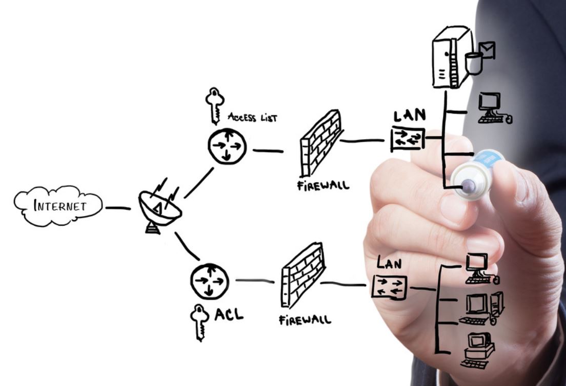
The complete network design is prepared by following the cisco’s multi-layered network architecture where we have multiple layers of devices. This architecture has three basic layers namely core, distribution, and access layer in which we place all the devices. The core layer consists of the router which connect the internal network to the external network. A firewall and a router are placed in the distribution layer where we can configure access control and most of the security measures. In the third layer of the network design consist of several switches, and wireless access points which are connected to the distribution layer router. These switches further connect the WAP which wirelessly connect the end user devices such as computer systems, servers, printers, VOIP, etc. Following this concept, we develop the physical and logical network topology diagram which fulfil all the need of the organization.
Deliverables
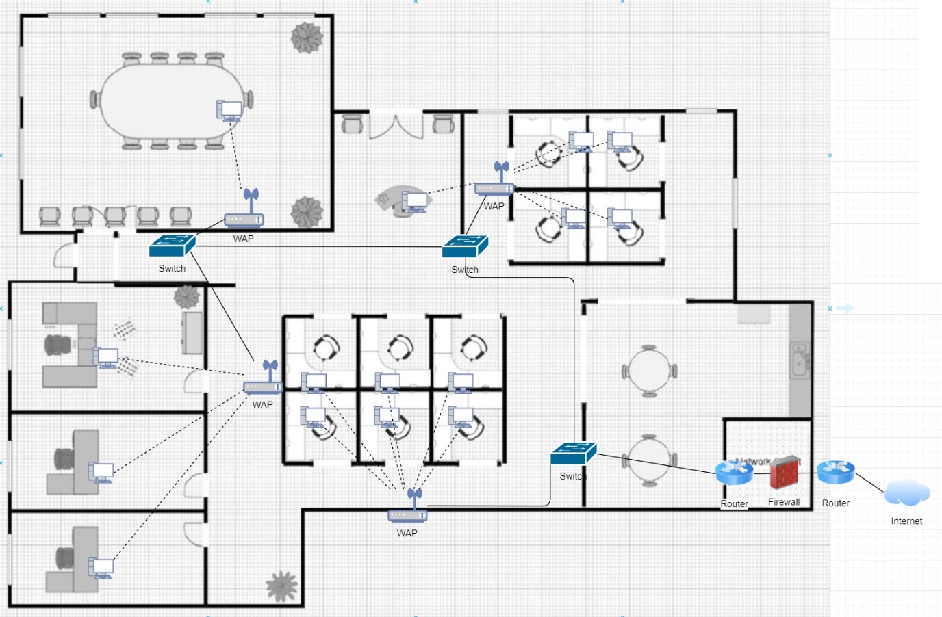
Physical network topology
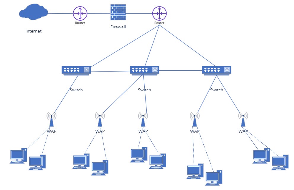
Logical network topology
The logical network design is presented in the above figure. In this design, we can see the segmentation of network for different departments or parts of the network. For this purpose, we created several VLANs which are connected to switches through the wireless access points
Equipment datasheet
Here is the list of network equipment used in this network design –
| Name of device | Unit required (approx.) |
| Router | 2 |
| Switch | 3 |
| Firewall | 1 |
| Wireless access points | 5 |
| Cable | 400 meters |
| Computer systems | 15 |
Device specification
Here is the description of the used devices in the network topology –
| Router |
A router is a networking device that is used to transfer data from one router to another router. It is used to receive, analyze and forward the data packets in the network with the help of the internet. In this design, we will use cisco’s 4321 integrated circuit router. You can see the router placement in the design diagram. It is a good router that provides lots of functionalities. It capable of providing a speed of 50 Mbps to 100Mbps. It has an 8 Gb flash memory that provides the speed to the network. It also supports wireless connectivity. The 4321 routers have modular network interfaces that can perform various tasks efficiently like load balancing, removal of interfaces, resiliency in network etc. |
| Switch |
The switch is a networking device that is used to receive and transfer data with the help of packet switching. It operates at the data link layer of the OSI model. It receives the incoming packets and transfers them to the destination address. Some tasks are performed by the switch like routing and the access control. We have used cisco’s 3560 CX catalyst switch to design the network for the organization. This is the latest switch and is capable of handling all the tasks required by the network. It can handle all the small to medium size enterprise networks very easily. It can easily provide a higher data rate of up to 10 Gbps. |
| Firewall |
It is a network security system that is used to monitor the network activities and protect the network from outside unauthorized activity or access. It is a barrier between the trusted and non-trusted network. It is mostly used in the network to provide security to the organization network and the data. Firewalls can be hardware devices as well as software. Firewall rules are configured by the network admin according to the requirement of the organization. We have used cisco’s ASA 5585 X firewall in this network design to provide better security. It can support access control, policies for monitoring and agreements. It is also capable of providing safety to critical data centre resources. |
| Cable |
Cables are used to connect different hosts in the network. There are lots of cables available in the market. we have used the CAT 6a twisted pair cables in this network design. These are the latest cables that can provide a transfer rate that is between 250 to 500 MHz It uses the RJ 45 connectors for connectivity. |
IP address scheme
The IP addressing scheme is presented here – Read more…
| Device | Interface | IP address | Subnet mask |
| Core router | To firewall | 10.10.10.1 | 255.255.255.252 |
| To ISP (internet) | ISP defined | N/A | |
| Distribution router | To firewall | 20.20.20.1 | 255.255.255.252 |
| Internal | |||
| Sub-interface 1 | 172.16.1.1 | 255.255.255.0 | |
| Sub-interface 2 | 172.16.2.1 | 255.255.255.0 | |
| Sub-interface 3 | 172.16.3.1 | 255.255.255.0 | |
| Sub-interface 4 | 172.16.4.1 | 255.255.255.0 | |
| Sub-interface 5 | 172.16.5.1 | 255.255.255.0 | |
| Firewall | To core router | 10.10.10.2 | 255.255.255.252 |
| To distribution router | 20.20.20.2 | 255.255.255.252 | |
The VLAN details are here –
| VLAN | Name of VLAN | IP address range | Subnet mask | Default gateway |
| VLAN 10 | Department-1 | 172.16.1.2-254 | 255.255.255.0 | 172.16.1.1 |
| VLAN 20 | Department-2 | 172.16.2.2-254 | 255.255.255.0 | 172.16.2.1 |
| VLAN 30 | Department-3 | 172.16.3.2-254 | 255.255.255.0 | 172.16.3.1 |
| VLAN 40 | Department-4 | 172.16.4.2-254 | 255.255.255.0 | 172.16.4.1 |
| VLAN 50 | Department-5 | 172.16.5.2-254 | 255.255.255.0 | 172.16.5.1 |
Guest wireless access
A wireless access point is configured and place at the entry gate of the building where all the visitors or guests are entering into the building area. A sitting place is there for guests to facilitate them. The wireless access point is configured here with no security so that guests can connect and use the network. Although this network has no authentication, but it is highly secured network due to the high chance of cyber-attack and an open point for intruders.
Budget and schedule
Labor proposal
Here is the estimated labor cost summary required to develop and configure this network topology –
| Phase description | Hours | Rate | Subtotal | Expenses | Total |
| 1 – Network design | 15 | $500 | $7,500 | $5,000 | $12,500 |
| 2 – Equipment cost purchase price | 12 | $600 | $7,200 | $78,000 | $85,200 |
| 3 – Implementation | 25 | $700 | $17,500 | $26,000 | $43,500 |
| Labor cost total | 52 hours | $32,200 | $1,09,000 | $1,41,200 |
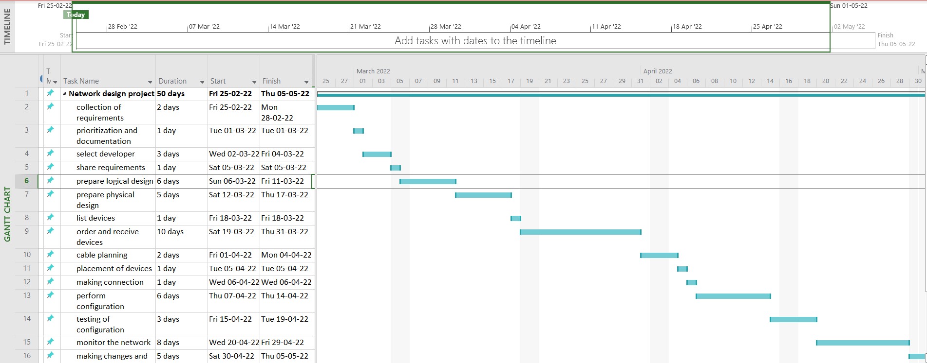
Schedule
Here is the complete schedule of the project
Budget
An approximate budget of this project is $1,41,200 which include the capital expenditure cost and operational expenditure cost. The capital expenditure cost is calculated approx. $1,09,000 and the operational expenditure cost is calculated approx. $32,200 which are under the expected cost of the organization.
Reference
Cisco ISR integrated circuit router, https://www.cisco.com/c/en/us/support/routers/4321-integrated-services-router/model.html
Cisco’s 3560 CX catalyst switch, https://www.cisco.com/c/en/us/support/switches/catalyst-3560-cx-series-switches/series.html