Part 2
OSI reference model
Modern computer networks are designed in a highly structured way. To reduce their design complexity, most networks are organized as a series of layers, each one built upon its predecessor. The OSI reference model is based on a proposal developed by the International Organization for Standardization (ISO). The model is called ISO/OSI (Open Systems Interconnection) reference model because it deals with the connecting open systems. These are the systems that are open for communication with other systems.
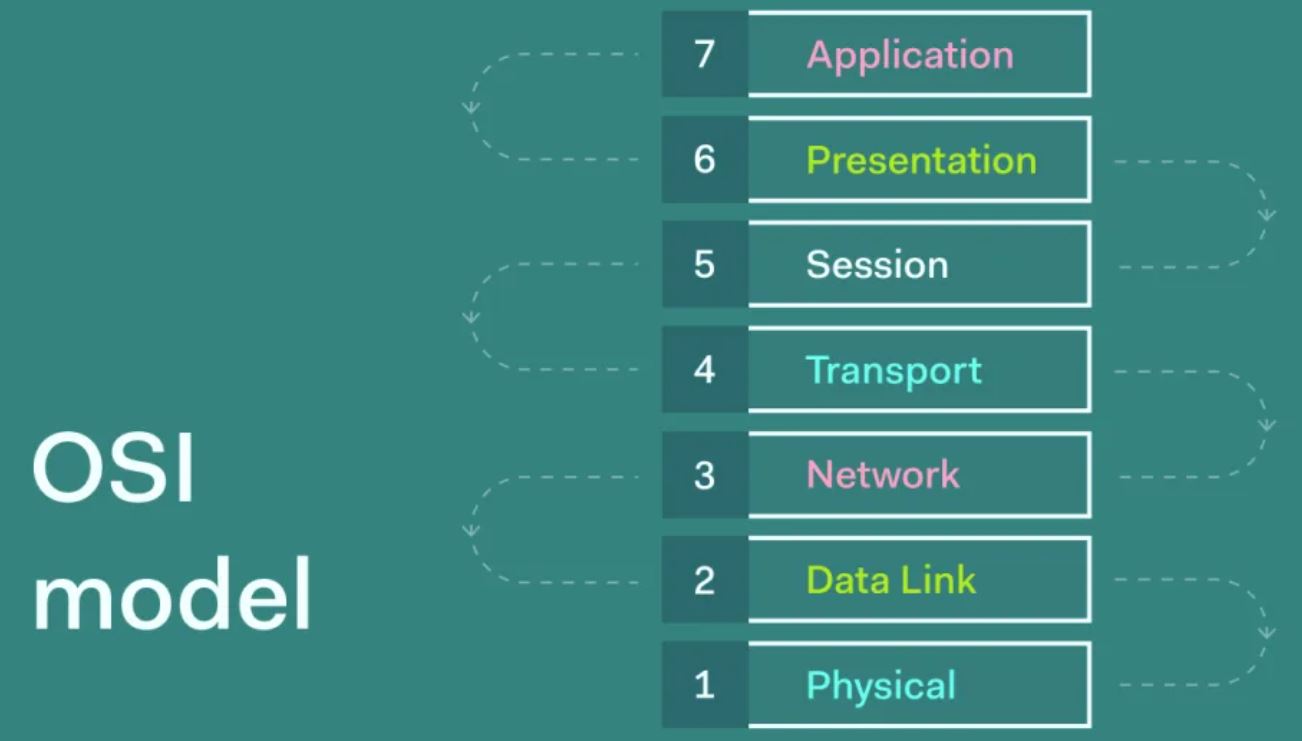
The Open System Interconnect model (OSI) can be viewed, as asset of functional layers connecting the rules that network and stations must follow to exchange information. A standard protocol lists specific rules that must apply at a certain layer (or layers) across different types of equipment manufactured by different vendors. There are seven layers of OSI model. The OSI reference model is a concept that describes how data communication should take place. It provides common basis for the coordination of standards development for system interconnection, while allowing existing standards to be placed into perspective within the overall model.
The OSI model has seven layers. The principles that are applied to arrive at the seven layers are as follows:
- A layer should be created where a different layer of abstraction is needed.
- Each layer should perform a well-defined function.
- The function of each layer should be chosen with an eye towards defining internationally standardized protocols.
- The layer boundaries should be chosen to minimize the information flow across the interfaces.
- The number of layers should be large enough that distinct functions need not to be thrown together in the same layer out of necessity, and small enough that the architecture does not become unwieldy.
OSI Model Features
- The international organization introduced the OSI layer for standardization (ISO) in 1984 in order to provide a reference model to make sure products of different vendors would interoperate in networks.
- OSI is short or open system interconnection.
- The OSI layer shows what needs to be done to send data from an application on one computer, through a network, to an application on another computer, not how it should be done.
- A layer in the OSI model communicates with three other layers: the layer above it, the layer below it, and the same layer at its communication partner.
- Data transmitted between software programs passes all 7 OSI layers.
- The application, presentation and session layers are also known as upper layers.
- The data link and physical layers are often implemented together to define LAN and WAN specifications.
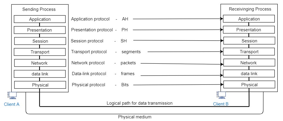
Data Encapsulation process
- Data encapsulation is the process of adding a header to wrap the data that flows down the OSI model.
- Each OSI layer may add its own header to the data received from above. (From the layer above or from the application layer)
- The 5 steps of data encapsulation are:
- The application, presentation and session layers create data from user’s input.
- The transport layer converts the data to segments.
- The network layer converts the segments to packets (or datagrams).
- The data link layer converts the packets to frames.
- The physical layer converts the frames to bits.
- At the sending computer the information goes from top to bottom while each layers divides the information received from upper layers to the smaller pieces and adds a header. At the receiving computer the information flows up the model discarding the corresponding header at each layer and putting the data.
The below table shows the different types of OSI layers, their functions, protocols and network components used at that layer:
| Layer | Function | Protocols | Network component |
| Application layer | – Used for applications, specifically written to run over the network
– Allow access to network services that support applications – Directly represents the services that directly support user applications – Handle network access, flow control and error recovery – Example apps are file transfer, e-mail, NetBIOS based applications |
DNS, FTP, TFTP, BOOTP, SNMP, rlogin, SMTP, MIME, NFS, FINGER, telnet, NVCP, APPC, AFP, SMB | Gateway |
| Presentation layer | – Translate from application to network format and vice-versa
– All different formats from all sources are made into a common uniform format that the rest of the OSI model can understand – Responsible for protocol conversion, character conversion, data encryption, decryption, expanding graphics, data compression – Sets standards for different systems to provide seamless communication from multiples protocol stacks – Not always implemented in a network protocol |
Gateway redirector | |
| Session layer | – Establish, maintain and end sessions across the network
– Responsible for name recognition, so only the designation party can participate in the session – Provide synchronization service by planning check points in the data stream – Manage who can transmit data at a certain time and for how long |
NetBIOS, names pipes, mail slots RPC | Gateway |
| Transport layer | – Additional connection below the session layer
– Manage the flow control of data between parties across the network – Divide stream of data into chunks or packets, the transport layer of the receiving computer reassembles the message from packets – Data is divided in to identical units – Provide error checking to guarantee error free data delivery with no duplication – Provide acknowledgement of successful transmission, requests retransmission if some packets don’t arrive error free – Provide flow control and error handling |
TCP, ARP, SPX, RARP, NWLINK, NetBIOS, NeTBEUI, ATP | Gateway, advance cable tester, brouter |
| Network layer | – Translate logical network addresses and names to their physical address
– Responsible for addressing, routing, manage and resolve network issues, like packet switching, congestion, routing – Reassembling of data chunks – Stamping or labeling of address for each layer |
IP, ARP, RARP, ICMP, RIP, OSPF, IGMP, IPX, Nwlink, Netbeui, | Brouter, frame relay device, router, ATM switch |
| Data link layer | – It turns packets in to raw format (0 and 1) and at the receiving end, turns bits into packets
– Handling of data frames between network and physical layer – Responsible for error free transfer of frames via physical layer – Define the methods used to transmit and receive data on the network. It consists of wiring to NIC used to send and receive signals, detect error in physical media |
LLC –
Error correction, flow control, link control, logical link control
MAC – Communication with NIC, media control, CSMA/CD, token bus, token ring |
Bridge, switch, ISDN router, intelligent hub, NIC |
| Physical layer | – Transmit raw bit stream over physical cable
– Define cable, card and other physical aspects – Define NIC attachment to hardware – Define techniques to transfer bit stream to cable |
IEEE 802
IEEE 802.0 ISO 2110 ISDN |
Repeater, multiplexer, hubs, TDR, amplifier, oscilloscope |
Resource:
https://aws.amazon.com/what-is/osi-model/
https://study-ccna.com/encapsulation/